1. Background
The most important connection method of wind turbine is bolt connection. The quality of thousands of bolts directly affects the safety and reliability of wind turbine operation. Due to the variety and quantity of wind power bolts, providing a fast and effective bolt detection method is an important means to ensure the safe operation of wind turbine.
2. Classification of wind power bolts
Most of the components of wind turbine generator set are connected and fastened by high-strength fastening bolts, and the main components are located in impeller, yaw, tower drum and other parts; wind power bolts can be divided into tower bolts, yaw bolts, spindle connecting bolts, blade bolts (inner and outer rings), etc. according to the shape of bolts, they can be divided into hex bolts, hex head bolts, stud bolts, etc.
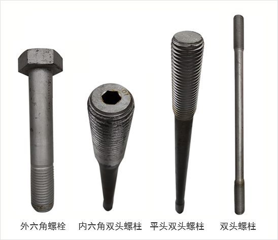
Figure 1 Wind power bolts
3. Phased array 3D total focus (TFM) detection method for wind power bolts
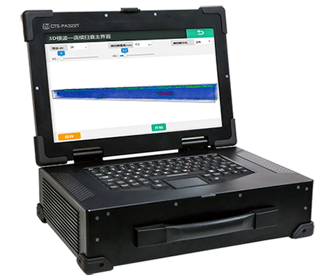
Figure 2 Phased array total-focus real-time 3D ultrasonic imaging system--CTS-PA322T
The CTS-PA322T system is equipped with a special probe for wind power bolts. When detecting wind power bolts, it only needs to operate according to the regulations. Placing the probe at the end of the bolt (both ends) without moving the probe. The CTS-PA322T system can collect all the internal information of the tested bolt and output the 3D detection image of the detected bolt in real time. The system provides the function of defect analysis and storage, which can accurately locate and quantitatively measure the internal defects of the detected bolts.
Wind power bolt detection case:
In order to verify the feasibility of phased array total focus real-time 3D ultrasonic imaging system CTS-PA322T flaw detection equipment and its inspection results, we compared the 3D imaging of the equipment with conventional phased array B-scan images (linear array probe, chrysanthemum array probe) and conventional A-scan image.
> Case 1: Tower bolt
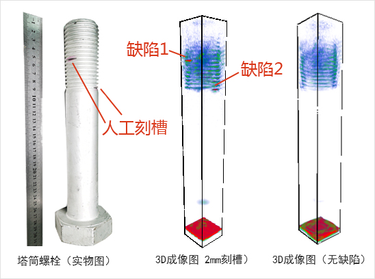
Fig. 3 3D total focusing inspection image of tower bolt
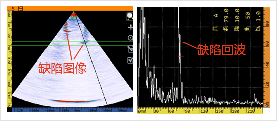
Fig. 4 Conventional phased array inspection image of tower bolt
> Case 2: Blade bolt
This blade bolt has natural crack defect, which is small and invisible. The test results are shown in the figure:
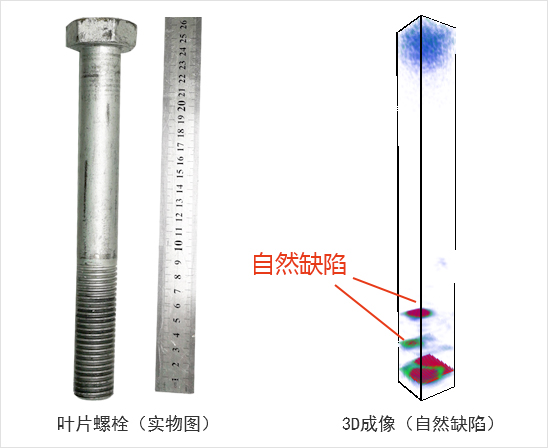
Fig. 5 3D total focusing inspection image of blade bolt

Fig. 6 Conventional phased array inspection image of blade bolt
> Case 3: Blade bolt
This blade bolt was processed with two 2mm groove defects. The inspection results are as follows:
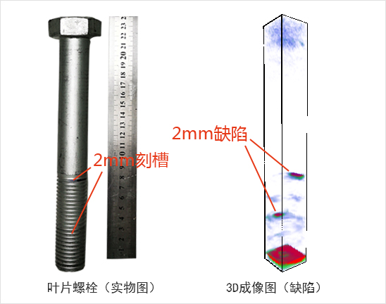
Fig. 7 3D total focusing inspection image of blade bolt

Fig. 8 Conventional phased array inspection image of blade bolt
>Case 4: Hexagon blade bolt
The special chrysanthemum array probe developed by our company is used to detect the hexagon black bolt. Due to the large aspect ratio of the detected bolt, there are symmetrical pseudo waves during detection. The bolt is machined with a 2mm groove defect.
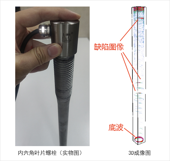
Fig. 9 3D total focusing inspection image of hex bolt
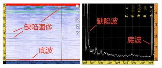
Fig. 10 3D total focusing inspection image of hex bolt
>On-site inspection case: Natural defect detection of M28 × 240 blade-pitch bearing inner ring bolt
During the full inspection of 1.5MW wind power bolts in a wind farm, five bolts with large crack defects were found in the inner ring bolts of blade-pitch bearing, and the bolts were disassembled and replaced on site. Among the removed bolts, one bolt was found to be broken during the unloading process, one was obvious cracked and three cracks could not be identified by naked eyes.
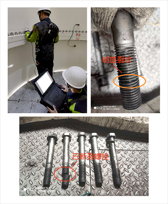
Figure 11 Cracked bolts detected and removed on site
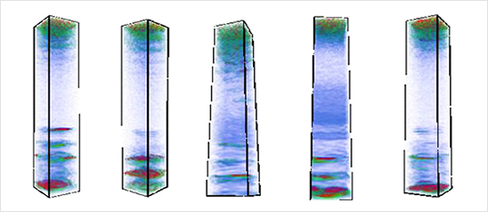
Figure 12 3D TFM image of on-site inspection
It can be seen from the above cases that, through the comparison of conventional A-scan inspection chart, conventional B-scan imaging and 3D TFM technology inspection image, although A-scan inspection chart can detect the location of defects, B-scan imaging and 3D TFM imaging can clearly display defects, for the detection of hex bolts, the defect wave in A-scan inspection image can only display part of the defect waveform, and in B-scan inspection, the characteristic difference between the inherent image of the structure and the crack image is not very obvious, both of which are easy to cause misjudgment or missed detection. However, 3D TFM imaging can clearly distinguish the crack defect image and the structure image. Stereoscopic image, simple defect recognition, and fast detection speed, which improves the effectiveness of detection.
4. Traditional detection method of wind power bolt
The NDT methods of bolts mainly include ultrasonic testing, magnetic particle testing, penetrant testing and eddy current testing. However, only ultrasonic testing can meet the requirements of in-service testing of wind power bolts. Ultrasonic testing can also be divided into conventional ultrasonic testing and phased array ultrasonic testing.
> Conventional ultrasonic testing (UT)
Conventional ultrasonic testing mainly uses small angle longitudinal wave probe to detect bolts, and the detection results are judged by waveform. This method has certain testing experience requirements for inspectors, and is only applicable to the detection of some small-sized hex head bolts. For hex bolts, hexagon socket studs and longer bolts, this method cannot be used, and the detection efficiency is relatively low. It is the least recommended method in ultrasonic testing of wind power bolts in service.
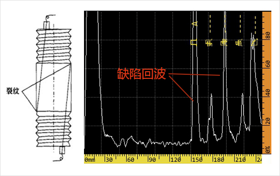
Figure 13 conventional ultrasonic testing of bolts
> Conventional phased array detection (PAUT)
The image judgment of conventional phased array detection is different from the waveform judgment of conventional ultrasonic detection. The 2D image visualization of detection results is more intuitive and has a wider detection range, which can basically cover the detection requirements of small MW wind power bolts.
Conventional phased array detection currently use two main scanning methods: one is to use linear array probe for S-scan or L-scan imaging detection (as shown in Fig. 3), but this method can only detect one section of the bolt at a time. To fully inspect the entire bolt, it is necessary to rotate the probe at least 180 degrees to realize full coverage, which reduces the detection efficiency.
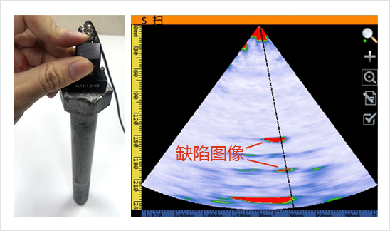
Figure 14 S-scan detection results
Another method is to use chrysanthemum array probe to detect (the detection results are shown in Fig. 4). This method does not need to rotate the probe and can improve the detection efficiency. Although the results of chrysanthemum array probe detection can not directly reflect the crack depth, and can not detect the internal defects of bolts, the size matching requirements of probe and bolt specifications are relatively high, compared with conventional ultrasonic testing & conventional phased array, its detection results are more direct, and the detection range is wider, which can basically realize the detection of wind power bolts.
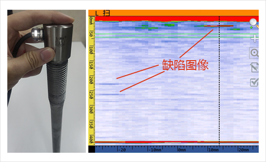
Figure 15 Testing results of chrysanthemum array detection
In conclusion, conventional ultrasonic and conventional phased array detection can be used for in-service inspection of bolts, but the requirements for inspectors are high and human factors are relatively large, while magnetic powder and penetration are not conducive to in-service inspection on site.
Advantages of 3D full focus technology:
● In the 3D space, the internal defect information of the detected workpiece is collected from different spatial angles, and the information collection is more sufficient. The internal defects of the bolt can be seen directly, and the imaging is intuitive and reliable, so as to avoid missing inspection of defects.
● Without moving the probes, the system can realize real-time 3D imaging of the whole bolt, and can be rotated to observe. The detection results are more intuitive. The system provides the function of defect analysis and storage, which can accurately locate and quantitatively measure the internal defects of the detected bolts.
● The detection time of a bolt is less than 2 seconds, high detection efficiency.


