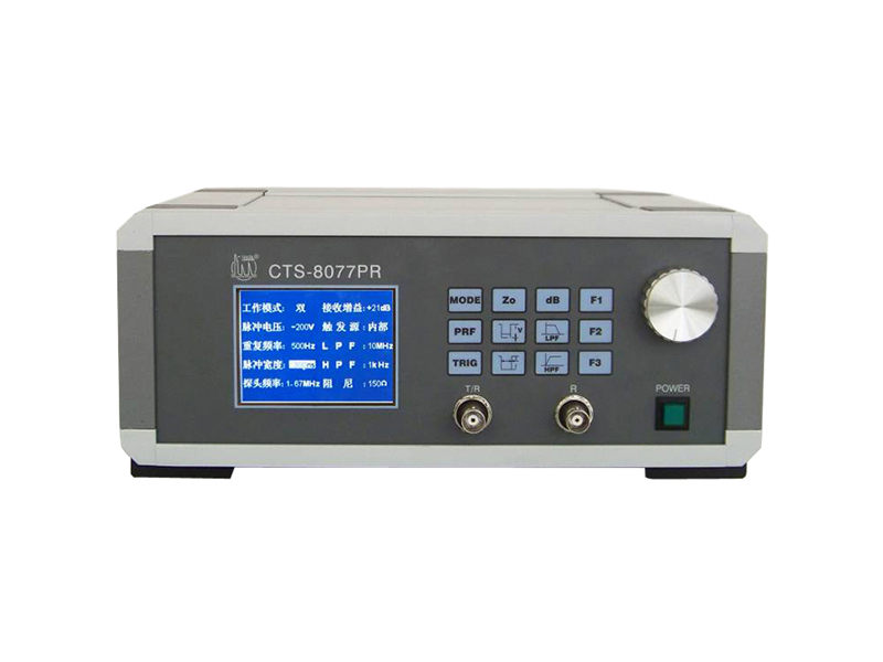


As a pulser-receiver developed by Shantou Goworld Co.Ltd. the CTS-8077PR lives up to the requirements of the transducer testing system by EN12668:2000 standard.
As a pulser-receiver developed by Shantou Goworld Co.Ltd.CTS-8077PR lives up to the requirements of the transducer testing system by EN12668:2000 standard. It is featured by low-noise and broadband receiver-amplifier. Moreover it is equiped with advanced transmission circuit constituted by high-performance square wave pulser and high-voltage circuit.
Coupled with digital oscilloscopethis device can serve the function of assessing the acoustic property of ultrasonic probe and that of working out the performance index. It can also be applied in such occasions as ultrasonic flaw detecting system thickness gauging material charateristics measuring and so on.
Broadband square wave pulser.
Pulse width ranging adjustably from 25ns to 6500ns minimum step 5ns corresponding to the probes as from 80kHz to 20MHz.
Pulse Voltage varying adjustably from -25V to -400V by the step of 25V.
Optional pulse repetitive frequency with the highest up to 5 kHz.
Broadband (30MHZ) pulse receiver.
60dB RF Gains1 dB step to adjust.
50dB RF Attenuations 1dB step to adjust.
10MHz or 30MHz optional low-pass filter.
1kHz or 1MHz optional high-pass filter.
USB interface PC synchronized control and PC synchronized control software and user-developing package.
Performance comparison of the 8077PR and the famous instruments from foreign countries
1. Transmitted waveform comparison between the two instruments (Default damping vaule of 50Ω for the both instruments)
| X077PR | CTS-8077PR | |
| 100v 25ns |  | 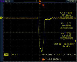 |
| 200v 25ns |  | 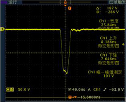 |
| 300v 25ns | 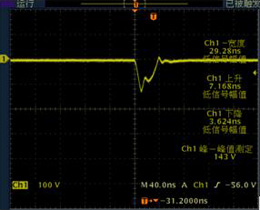 | 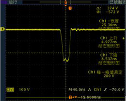 |
| 100v 50ns | 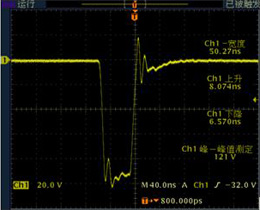 | 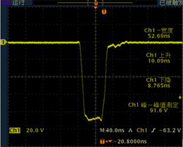 |
| 200v 50ns | 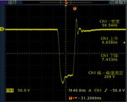 | 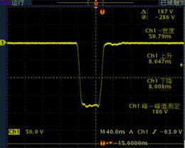 |
| 100v 100ns | 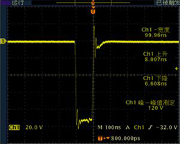 |  |
| 200v 100ns | 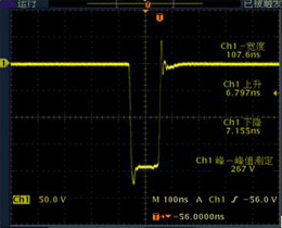 |  |
| 200v 200ns | 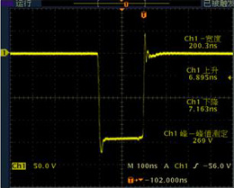 |  |
| 100v 500ns | 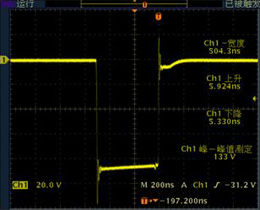 | 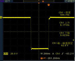 |
| 300v 500ns | 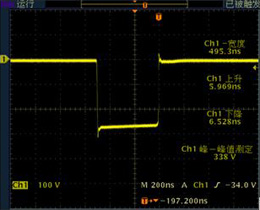 | 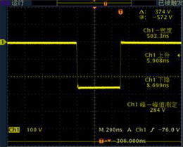 |
| 100v 1000ns | 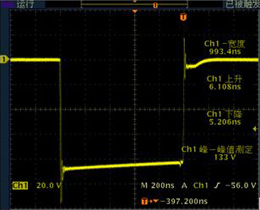 | 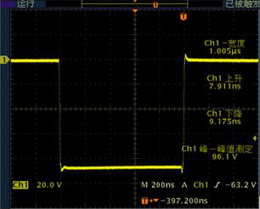 |
| 200v 1000ns | 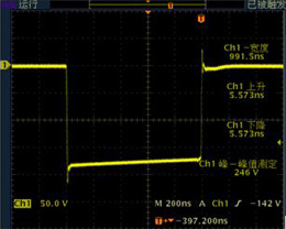 | 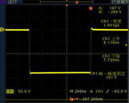 |
| 300v 1000ns |  | 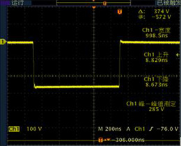 |
2. Waveform comparison by Energizing TOFD probe
| X077PR | CTS-8077PR | |
| 10MHZ Voltage:200v Pluse:50ns | 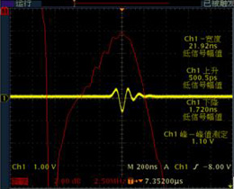 |  |
Center Frequency:8.28MHz Absolute bandwidth:7.5MHz | Center Frequency:7.5MHz Absolute bandwidth:8.6MHz | |
| 5MHZ Voltage:100v Pluse:100ns |  |  |
Applications:
● Thickness guage
● Velocity measurement
● Spectrum analysis
● Transducer properties testing
● Other materials and process monitoring
● As EN-standard according probe-calibrating system.
Take the UT transducers (probes) for example:
To test the pulse width of the echo wave center frequency -6dB relative bandwidth and relative pulse sensitivity of echo wave by the CTS-8077 pulser-receiver and "Goworld-ed" probe-testing software in concert.
Tip 1 for the organization:
1. The CTS-8077PR T/R BNC socket is connected to the ultrasonic transducer through the probe cable (coaxial shielded wire) and BNC three-way socket working mode: Mono.
2.The OSC connected with PC through cross network cable and proof-reading of the data acquired by the PC from OSC.
3.The CH1 (channel 1)-probe connected with the BNC socket. As shown in Figure 1.
The characteristic of this connection in Figure 1 is that the OSC probe acquires output signals from the transducer without passing through the PR which requires no bandwith limit on the receiving circuit of the PR suitable for the probes with high sensitivity.
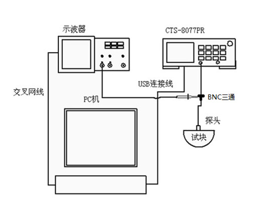
Figure 1
Testing Process
1.In reference to Figure 1 put all the units in their place and make sure they run well.
2.Make sure there's waveform data to the PC from the OSC.
3.Set up the OSC turn on "CH1" and "MATH" and set the "MATH" as "FFT algorithm" set the signal source as "CH1".
4.Set the working mode of CTS-8077PR as "Mono" and set other paras according to the transducer. As we're now experimenting the 2.5P20 Series the settings should be followed as:
Working Mode:Mono;Gain:0dB;Pulse Voltage:-200V;Triggering Source:Inner;
PRF:500Hz;LPF:30MHz;Pulse Width:200ns;HPF:1kHz;Damping:50Ω;
After setting open the probe-testing software (for details please contact the company customer service)
1) Complete the registration of the probe test software (see software instructions for details)
2) Complete the connection between the software and the OSC (see software instructions for details)
3) Set relevant parameters
The parameter setting page is shown in Figure 2 including the PR parameters probe information angle/K value others signature information and report ti
Users can fill in according to the actual situation of the test. Among them the parameters of the PR parameter column can be filled in by the user or can be used with our PR to automatically read the parameters of the instrument. Just use the USB cable to connect with the computer and click the read-setting button on the parameter interface to automatically read the instrument parameters.
*Note: If you use the software to automatically read the parameters on the CTS-8077PR instrument the probe test software can only be used under the Windows XP operating system.
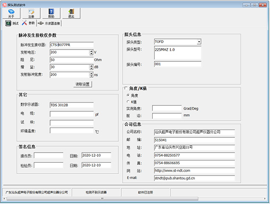
Figure 2
4)Probe test
The test interface is shown in Figure 3. Click “Testing”. After the test is successful the test result data will be displayed in the test result column. The parameters displayed in the test instrument probe and test condition combo boxes are the parameters entered on the parameter page. The related testing results are the data calculated by the test. So far the probe test is completed just save the test result.

Figure 3


