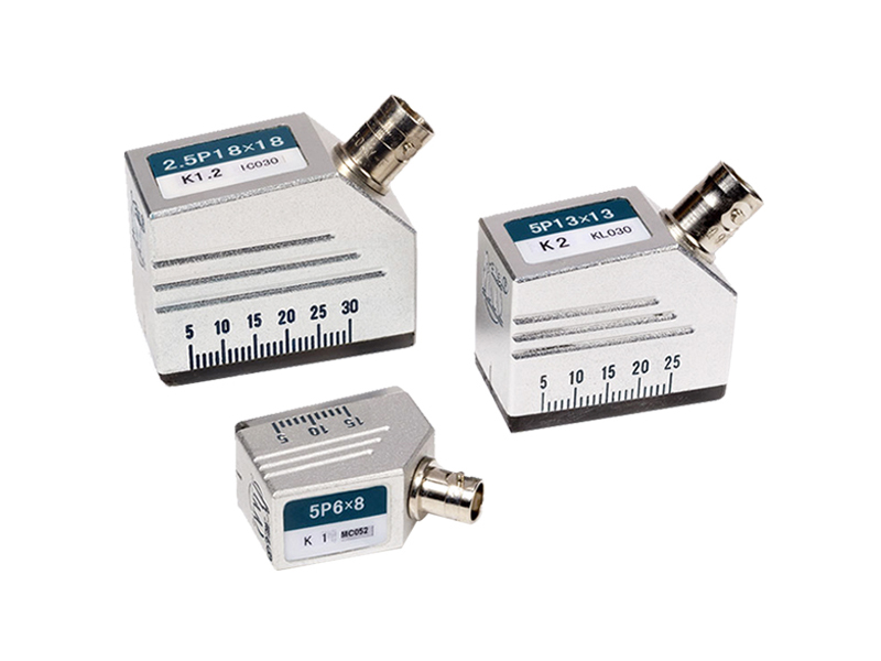


Angle beam probes introduce refracted shear waves into a test piece and they consist of wedges, piezoelectric elements, sound-absorbing materials, cases, receptacles and other components.
Angle beam probes introduce refracted shear waves into a test piece and they consist of wedges, piezoelectric elements, sound-absorbing materials, cases, receptacles and other components.
The piezoelectric elements are used for transmitting and receiving the ultrasonic waves.
The wedges are used for converting the ultrasonic wave modes, when an incident angle is between the first critical angle and the second critical angle, there are only transverse waves in work pieces according to the refraction law of the ultrasonic waves in the different acoustic impedance interfaces.
The sound-absorbing materials are used to absorb the noises from the back of the elements and the offside of the wedges.
The cases are used as a support, protection and electromagnetic shielding materials.
The receptacles are the electric signal interfaces for connecting an instrument with a probe cable.
The size of the refraction angle of the angle beam probes is indicated by the K value.
To an angle beam probe, its sound beams incline toward the surface of the probe, therefore, these angle beam probes can be used to detect the areas that the direct sound beams can not reach or the areas that introduce an angle between the flaw direction and the detection surface.
Angle beam probes (Large size elements )
| Frequency(MHz) | Element size(mm) | Type | Case | Receptacle |
| 1 | 13*13 | 1P13*13 K1 | B2 | Q9 |
| 1P13*13 K1.5 | ||||
| 1P13*13 K2 | ||||
| 1.25 | 13*13 | 1.25P13*13 K0.8 | B2 | |
| 1.25P13*13 K1 | ||||
| 1.25P13*13 K1.5 | ||||
| 1.25P13*13 K2 | ||||
| 1.25P13*13 K2.5 | ||||
| 1.25P13*13 K3 | ||||
| 13*13 | 1.25P18*18 K0.8 | B1 | ||
| 1.25P18*18 K1 | ||||
| 1.25P18*18 K1.5 | ||||
| 1.25P18*18 K2.0 | ||||
| 1.25P18*18 K2.5 | ||||
| 1.25P13*13 K3 | ||||
| 2.5 | 10*16 | 2.5P10*16 K0.8 | B2 | |
| 2.5P10*16 K1 | ||||
| 2.5P10*16 K2.5 | ||||
| 2.5P10*16 K2 | ||||
| 2.5P10*16 K2.5 | ||||
| 2.5P10*16 K3 | ||||
| 13*13 | 2.5P13*13 K0.8 | B2 | ||
| 2.5P13*13 K1 | ||||
| 2.5P13*13 K2.5 | ||||
| 2.5P13*13 K2 | ||||
| 2.5P13*13 K2.5 | ||||
| 2.5P13*13 K3 | ||||
| 18*18 | 2.5P18*18 K0.8 | B1 | ||
| 2.5P18*18 K1 | ||||
| 2.5P18*18 K2.5 | ||||
| 2.5P18*18 K2 | ||||
| 2.5P18*18 K2.5 | ||||
| 2.5P18*18 K3 | ||||
| 5 | 10*16 | 5P10*16 K1 | B2 | |
| 5P10*16 K0.8 | ||||
| 5P10*16 K1.5 | ||||
| 5P10*16 K2 | ||||
| 5P10*16 K2.5 | ||||
| 5P10*16 K3 | ||||
| 13*13 | 5P13*13 K0.8 | B2 | ||
| 5P13*13 K1 | ||||
| 5P13*13 K1.5 | ||||
| 5P13*13 K2 | ||||
| 5P13*13 K2.5 | ||||
| 5P13*13 K3 |
*The angle beam probes are divided into the ordinary front edge probes and the short front edge probes.
*The other angle probes are manufactured on a special basis to customer specifications. Contact us to discuss applications.
Small angle beam probe
| Frequency(MHz) | Element size(mm) | Type | Case | Receptacle |
| 2.5 | 8*12 | 2.5P8*12 K0.8 | B3 | Q9 |
| 2.5P8*12 K1 | ||||
| 2.5P8*12 K1.5 | ||||
| 2.5P8*12 K2 | ||||
| 2.5P8*12 K2.5 | ||||
| 2.5P8*12 K3 | ||||
| 9*9 | 2.5P9*9 K0.8 | |||
| 2.5P9*9 K1 | ||||
| 2.5P9*9 K1.5 | ||||
| 2.5P9*9 K2 | ||||
| 2.5P9*9 K2.5 | ||||
| 2.5P9*9 K3 | ||||
| 5 | 8*12 | 5P8*12 K0.8 | ||
| 5P8*12 K1 | ||||
| 5P8*12 K1.5 | ||||
| 5P8*12 K2 | ||||
| 5P8*12 K2.5 | ||||
| 5P8*12 K3 | ||||
| 9*9 | 5P9*9 K0.8 | |||
| 5P9*9 K1 | ||||
| 5P9*9 K1.5 | ||||
| 5P9*9 K2 | ||||
| 5P9*9 K2.5 | ||||
| 5P9*9 K3 |
Miniature angle beam probes
| Frequency (MHz) | Element size(mm) | Type | case | Receptacle |
| 2.5 | 6*8 | 2.5P6*8 K0.8 | B4 | Q9 |
| 2.5P6*8 K1 | ||||
| 2.5P6*8 K1.5 | ||||
| 2.5P6*8 K2 | ||||
| 2.5P6*8 K2.5 | ||||
| 2.5P6*8 K3 | ||||
| 5 | 6*6 | 5P6*6 K0.8 | B5 | Q6 |
| 5P6*6 K1 | ||||
| 5P6*6 K1.5 | ||||
| 5P6*6 K2 | ||||
| 5P6*6 K2.5 | ||||
| 5P6*6 K3 | ||||
| 6*8 | 5P6*8 K0.8 | B4 | Q9 | |
| 5P6*8 K1 | ||||
| 5P6*8 K1.5 | ||||
| 5P6*8 K2 | ||||
| 5P6*8 K2.5 | ||||
| 5P6*8 K3 |
Small diameter probes
| Frequency (MHz) | Element size(mm) | Type | The refraction angles corresponding to the K values | Receptacle |
| 5 | 6*6 | 5P6*6 K2 | 38.7° | Q6 |
| 5P6*6 K2 | 45.0° | |||
| 5P6*6 K2 | 50.2° | |||
| 5P6*6 K2 | 56.3° | |||
| 5P6*6 K2 | 60.9° | |||
| 5P6*6 K2 | 63.4° | |||
| 5P6*6 K2 | 65.6° | |||
| 5P6*6 K2 | 68.2° | |||
| 5P6*6 K2 | 70.3° | |||
| 5P6*6 K2 | 71.6° |
Applications:
“P”for general applications--it is suitable for the test demanding high sensitivity and strong penetration of the instrument.
“C”for piezoelectric composite materials--it wins with its virtue of high sensitivity, high bandwidth, high resolution and high penetration which comtribute to the clear and precise results in testing coarse-grain and high attenuation material.


